No products in the cart.
Payment methods accepted
Unsure what Ethernet cable you need?
Look no further than our Ethernet Cable Finder. Answer a couple of questions and let trueBOT guide you to the perfect cable for any situation.
Still have questions? Check out our in-depth blogs, insightful white papers, and instructional videos on all things Ethernet cable and low voltage supplies.

Read: The Difference Between Cat6 vs Cat6A Ethernet Cable

Understand: Selecting the Correct Outdoor Ethernet Cable
Time to find coaxial cable and connectors for your install? Well, you are in the right spot!Check out our in-depth blogs, white papers, and instructional videos about everything going on in the low voltage industry and one of the best sources for coaxial information.
Have questions? Our networking experts have the answers!Check out our Cable Academy. for more information.
Read: The Difference Between Dual Shield vs Quad Shield Coaxial Cable
Understand: How To: Universal RG6 Compression F Connector on Quad Shield Coaxial Cable
Fiber Optic expertise at your fingertips.
Looking to deepen your understanding of fiber optic technology? Look no further than trueCABLE's Cable Academy. Our extensive collection of blogs, masterfully crafted by industry experts, offers a wealth of invaluable insights into the world of fiber optic cabling.
Have questions? Our networking experts have the answers.Check out our Cable Academy. for more information.
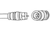
Read: Fiber Optic Splicing: Examining the Factors that Affect Splice Performance

Understand: Using Fiber Optics to Extend Your Ethernet Network Beyond Copper's Limits
Effortless cable management. Learn how we do it.
Low-voltage tools and accessories should keep your networking installations clean and organized. trueCABLE has a variety of high quality cable management tools, accessories and informative blogs for all your installation needs.
Check out our Cable Academy today and expand your knowledge.
Read: Copper Fabric Strips for Bonding Shielded Ethernet Cable
Understand: When Aliens Attack! Avoiding Ethernet Alien Crosstalk

Written by Ben Hamlitsch, trueCABLE Technical and Product Innovation Manager RCDD, FOI
Why MTP/MPO fiber patch cables? As fiber systems expand and require more scalability, MTP®/MPO cabling systems solve cable congestion in data centers or enterprises, because of its featured flexibility, reliability, and scalability. This is all well and good and solves the high bandwidth faster speeds issue. However, the spec engineer, or network integrator, faces another challenge; the crucial and very important design aspect of these array cabling systems and how to assure proper polarity using multi-fiber MTP®/MPO components from end to end. This is vital and extremely important when designing a cabling system using MTP®/MPO connections. Why? Maintaining the correct polarity across a fiber network ensures that a transmit signal from any type of active equipment will be directed to the receiving port of a second piece of active equipment. This is how information is sent and received in fiber cabling systems. To ensure that the system maintains the correct polarity there have been important guidelines or standards written to ensure proper polarity. The TIA 568 standard provides three methods, which we will cover in this article.
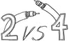
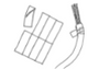
The MTP®/MPO Connector is a multi-fiber, high-performance fiber optic connector that has enhanced optical and mechanical performance. The unique design (shown below) of the MTP®/MPO connector ensures the accuracy of the polarity in the MTP®/MPO network system.
The Connector: An MPO/MTP connector has a key on the top or bottom of the connector body. There are two positions of the key — key up or key down. Key up position means that the key sits on top. When the key sits on the bottom, it is the key down position. Moreover, the fiber holes in the connector are numbered in sequence from left to right named as P1 (position 1), P2, etc. Each connector is additionally marked with a white dot on the connector body to designate the P1 side of the connector when it is plugged in. The MPO/MTP connector can be further divided into female connector and male connector. The former has no pins while the latter has two pins on the connector. The following picture shows the basic structure of MPO/MTP connector.

Figure 1: MTP®/MPO Connector.
But what is polarity? A general optical link requires two optical fibers to complete the entire transmission process, one as the TX and the other as the RX. The optical module has a receiving end (RX) and a transmitting end (TX). When in use, it is necessary to ensure that the receiving end and the transmitting end are connected to each other. The transmitting end and the receiving end at both ends of the optical link is known as polarity. Polarity defines direction the optical signal travels in the fiber. In common cabling systems, connectors such as LC and SC can easily be matched, so there is no polarity issue. They are simply two fibers: a transmitter, and a receiver. However, for pre-terminated, high-density MTP®/MPO cabling systems, polarity issues must be addressed.
The three methods for proper polarity defined by TIA 568 standard are called Method A, Method B, and Method C. To match these standards, three types of MTP® fibers with different structures named Type A, Type B, and Type C are being used for the three different connectivity methods. First, we will discuss the three cable types, and then the three connectivity methods.
Type A MTP® Cables: Type A cables, also known as straight cables, are straight-through cables with a key-up MTP® connector on one end and a key-down MTP® connector on the opposite end. This makes the fibers at each end of the cable have the same fiber position. For example, the fiber located at position 1 (P1) of the connector on one side will arrive at P1 at the other connector. The fiber sequence of a 12 fiber MTP® Type A cable is shown below:

Type B MTP® Cables: Type B cables (reversed cables) uses key-up connectors on both ends of the cable. In this Method the fiber positions are reversed at each end. The fiber at P1 at one end is mated with fiber P12 at the opposing end. The following picture shows the fiber sequences of a 12 fiber Type B cable.

Type C MTP® Cables: Type C cables (pairs flipped cables) looks like Type A cable with one key-up connector and one key-down connector on each side. However, in Type C each adjacent pair of fibers at one end are flipped at the other end. For example, the fiber at position 1 on one end is shifted to position 2 at the other end of the cable. The fiber at position 2 at one end is shifted to position 1 at the opposite end, and so forth. The fiber sequence of Type C cables is shown in the following image.

Different polarity methods use different types of MTP® trunk cables. However, all the methods should use duplex patch cables to achieve the fiber circuit. The TIA standard also defines two types of duplex fiber patch cables terminated with LC or SC connectors to complete an end-to-end fiber duplex connection: A-to-A type patch cable—a cross version and A-to-B type patch cable—a straight-through version.


The following part illustrates how the components in the MTP® system are used together to maintain the proper polarization connectivity, which is defined by TIA standards.
Method A: In Method A, type-A MTP® cable connects an MTP® module on each side of the link. In Method A, two types of patch cords are used to correct the polarity. The patch cable on the left is standard duplex A-to-B type, while on the right a duplex A-to-A type patch cable is used.

Method B: In method B, Type B MTP® cable is used to connect the two modules on each side of the link. The fiber positions of Type B cable are reversed at each end. Therefore, standard A-to-B type duplex patch cables are used on both sides.

Image by TIA 568B.3-E Standard document
Method C: A pair-reversed method C cable is used in Method C connectivity to connect the MTP® modules on each side of the link. Patch cords at both ends are the standard duplex A-to-B type.

Image by TIA 568B.3-E Standard document
It is very important that careful consideration be taken when adding MTP®/MPO cables to existing cabling in the network data center or enterprise application. Why? When fiber patch cords have different polarity and gender, it can be very easy to impact your cabling system transmission signal, rendering your entire cable link inoperable. That is why it is so important that IT staff and cabling technicians are very careful when replacing any patch cords in the field in an MTP®/MPO cabling system. Those who don’t understand polarity or are in a rush to get equipment up and running can potentially use the wrong patch cord and greatly impact the cable network.
Where there are A-to-A type patch cables and A-to-B type patch cables, there are three general types of array (multi-fiber) cable assemblies. It is noted that the alignment pins on the MTP®/MPO connectors are important for maintaining the correct polarity. Therefore, it is necessary to make sure of proper pin position before you connect MTP®/MPO fiber with patch cables.
A-to-B type LC/SC duplex patch cable is the standard crossover cable that maps the TX port to the RX port. With the crossover the A-to-B type patch cable maintains proper polarity. And MTP® trunk cable Type B reverses the fiber positions at each end (1 to 12 and 12 to 1) and the connector keys are both oriented key up. This kind of cable connection is recommended to keep proper type B MTP®/MPO polarity.
The selection of the MTP®/MPO Cassette will also determine the choice of MTP®/MPO cable. It is best to choose a cassette with proper alignment pins to ensure that the MTP®/MPO cassettes can perfectly mate with the MTP®/MPO connectors at either end of MTP®/MPO cables. In addition, the rear of the adapter mounted on the cassette defines it as either Method A or Method B to correspond with the TIA standard.
More and more network designers are using MTP®/MPO components to satisfy the increasing requirement for higher transmission speeds. When it comes to the design side of the MTP®/MPO application one of the big problems—polarity, can be solved by selecting the right types of MTP® cables, MTP® connectors, MTP® cassettes and fiber optic cables. Whichever cabling solution you choose, the three different polarity methods can be applied according to the system requirements in different cabling applications.
STAY CONNECTED!
trueCABLE presents the information on our website, including the “Cable Academy” blog and live chat support, as a service to our customers and other visitors to our website subject to our website terms and conditions. While the information on this website is about data networking and electrical issues, it is not professional advice and any reliance on such material is at your own risk.