No products in the cart.
Payment methods accepted
Unsure what Ethernet cable you need?
Look no further than our Ethernet Cable Finder. Answer a couple of questions and let trueBOT guide you to the perfect cable for any situation.
Still have questions? Check out our in-depth blogs, insightful white papers, and instructional videos on all things Ethernet cable and low voltage supplies.

Read: The Difference Between Cat6 vs Cat6A Ethernet Cable
Understand: Selecting the Correct Outdoor Ethernet Cable
Time to find coaxial cable and connectors for your install? Well, you are in the right spot!Check out our in-depth blogs, white papers, and instructional videos about everything going on in the low voltage industry and one of the best sources for coaxial information.
Have questions? Our networking experts have the answers!Check out our Cable Academy. for more information.
Read: The Difference Between Dual Shield vs Quad Shield Coaxial Cable
Understand: How To: Universal RG6 Compression F Connector on Quad Shield Coaxial Cable
Fiber Optic expertise at your fingertips.
Looking to deepen your understanding of fiber optic technology? Look no further than trueCABLE's Cable Academy. Our extensive collection of blogs, masterfully crafted by industry experts, offers a wealth of invaluable insights into the world of fiber optic cabling.
Have questions? Our networking experts have the answers.Check out our Cable Academy. for more information.
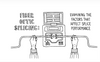
Read: Fiber Optic Splicing: Examining the Factors that Affect Splice Performance
Understand: Using Fiber Optics to Extend Your Ethernet Network Beyond Copper's Limits
Effortless cable management. Learn how we do it.
Low-voltage tools and accessories should keep your networking installations clean and organized. trueCABLE has a variety of high quality cable management tools, accessories and informative blogs for all your installation needs.
Check out our Cable Academy today and expand your knowledge.
Read: Copper Fabric Strips for Bonding Shielded Ethernet Cable
Understand: When Aliens Attack! Avoiding Ethernet Alien Crosstalk

Written by Ben Hamlitsch, trueCABLE Technical and Product Innovation Manager RCDD, FOI
Are you looking for ways to improve the performance of your fiber optic splices? If so, you've come to the right place. In this blog post, we'll examine the factors that affect splice performance, including intrinsic factors, extrinsic factors, and core diameter mismatch. We'll also discuss the different types of fiber optic splices, such as mechanical splices and fusion splices. Finally, we'll provide some tips on troubleshooting fusion splices.
The performance of a fiber optic splice is determined by a number of factors, including the quality of the fiber, the cleanliness of the splice, and the techniques used to make the splice. Intrinsic factors, such as the refractive index of the fiber, are those that are inherent to the fiber itself. Extrinsic factors, such as the presence of microbends, are those that are external to the fiber. Core diameter mismatch is a type of extrinsic factor that can cause significant loss in a splice.
By understanding the factors that affect splice performance, you can make informed decisions about the type of splice to use and the techniques to employ. This can help you achieve the best possible performance from your fiber optic splices.
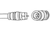
What is it that gets spliced onto a fiber optic cable strand or strands? We call it a fiber-optic pigtail. A fiber optic pigtail is a fiber optic cable with one end terminated with a factory-installed connector and the other end unterminated. As a result, the connector side can be connected to equipment, while the other side is fused in the case of fusion splicing and a mechanical connection in the case of mechanical splicing optical fiber cables. Fiber optic pigtails are used to connect fiber optic cables using fusion or mechanical splicing.
Fiber splicing is one way to join two optical fibers together so the light energy from one optical fiber can be transferred to another optical fiber. A fiber splice is the permanent connection of two optical fibers. Once the two optical fibers are joined with a splice, they cannot be taken apart and put back together, as they can if you join them using connectors. Fiber splices are typically employed for one of four reasons: to repair a damaged cable, extend the length of a cable, join two different cable types, or attach a pigtail. We'll talk about fiber pigtails later on in the article
How well a fiber splice performs depends on many variables. These variables can be broken into two groups: intrinsic factors and extrinsic factors.
An important thing to note and keep in mind is that optical fibers are not perfect, and variations between optical fibers can affect splice performance. These variations are referred to as intrinsic factors.
The performance of a fiber splice can also be affected by alignment and optical fiber mating issues that have nothing to do with the optical fiber. The factors that affect the alignment and mating of the optical fibers are referred to as extrinsic factors.
Even when fibers are manufactured within specific tolerances, slight variations still exist from one optical fiber to another. These variations can affect the performance of the splice even though the optical fibers are perfectly aligned when mated. The variations between two optical fibers that affect splice performance are referred to as intrinsic factors. Let us now look at the most common types of intrinsic factors.
A numerical aperture (NA) mismatch occurs when the NA of one optical fiber is different from the NA of the other optical fiber. If the NA of the transmitting fiber is larger than the NA of the receiving optical fiber, a loss may occur. However, a loss will not occur if the NA of the transmitting optical fiber is less than the NA of the receiving optical fiber.
Light must enter within a specified range defined by the acceptance cone or cone of acceptance. In order for light to be contained within a fiber, it must stay above the critical angle, or the angle at which it reflects off the boundary between the core and the cladding, rather than penetrating the boundary and refracting through the cladding.
To maintain the critical angle, light must enter within a specified range defined by the acceptance cone (or cone of acceptance). This region is defined by a cone extending outside the optical fiber core. Light entering the core from outside of the cone will either miss the core or enter at an angle that will allow it to pass through the boundary with the cladding and be lost. So the acceptance angle defines the acceptance cone. Light entering the core of the optical fiber at an angle greater than the acceptance angle may not propagate the length of the fiber. For light to propagate the length of the optical fiber, it must enter the core at an angle that does not exceed the acceptance angle.

The exact loss from an NA mismatch is difficult to calculate. Factors such as light source type, light source launch condition, optical fiber length, and bends in the optical fiber all affect the potential loss. It is possible to have an NA mismatch between two optical fibers with no loss from the mismatch.
A core diameter mismatch occurs when there is a difference in the core diameters of the two optical fibers. A core diameter mismatch loss results when the core diameter of the transmitting optical fiber is greater than the core diameter of the receiving optical fiber. A loss occurs when the light at the outer edge of the transmitting optical fiber core falls outside the diameter of the receiving optical fiber core. This light is lost in the cladding of the receiving optical fiber. Core diameter mismatch loss is typically only a concern with multimode optical fiber.
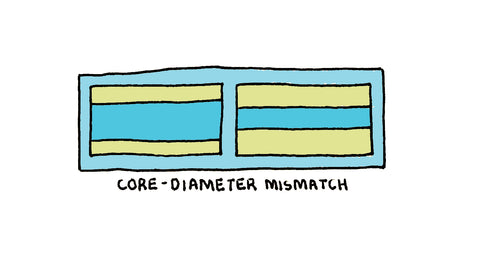
It is not uncommon for two multimode optical fibers with different core diameters to be spliced together. This is because multimode fiber has two common core sizes: 62.5um and 50um.
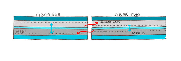
Mode field diameter is a concern when it comes to singlemode optical fiber. It describes the diameter of the light beam traveling through the core and a portion of the inner cladding. Values for the mode field diameter are defined by the wavelength, with the longer wavelength typically having 8.6 to 9.55um at 1310nm and 8 to 11um at 1550nm.
A mode field diameter mismatch occurs when there is a difference in the mode field diameters of two singlemode optical fibers. A mode field diameter mismatch loss results when the mode field diameter of the transmitting optical fiber is greater than the mode field diameter of the receiving fiber. A loss will occur when the optical fiber with the smaller mode field diameter will not accept all of the light from the optical fiber with the larger mode field diameter.
Cladding diameter mismatch occurs when the cladding diameters of the transmit and receive optical fibers are not the same. Cladding diameter mismatch loss occurs when the cores of the optical fiber are not aligned because the cladding diameters are not matching. A cladding diameter mismatch issue can cause the light exiting the core of the transmitting optical fiber to enter the cladding of the receiving optical fiber. The light entering the cladding is lost, causing attenuation.
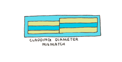
Ideally, the core in the cladding of the optical fiber are perfectly round and concentric, which means that they share a common geometric center. However, optical fibers are not perfect, and there will be concentricity variations. These concentricity variations can cause the optical fiber cores to misalign, causing a loss when the light exiting the core of the transmitting optical fiber enters the cladding of the receiving optical fiber.
Just as the core and cladding of an optical fiber may not be perfectly concentric, they may also not be perfectly circular. The non-circulatory nature of the core will cause a loss when light from the core of the transmitting optical fiber enters the cladding of the receiving optical fiber.

Cladding that is non-circulatory may cause loss when it causes part of the core of the transmitting optical fiber to align with the cladding of the receiving optical fiber. Any light that injures the cladding of the receiving optical fiber will be lost, causing attenuation.
Note that the amount of loss depends on the alignment of the elliptic curves of the two cores. Maximum loss occurs when the long or major axes of the cores are at right angles to one another, and minimum loss occurs when the axes of the cores are aligned.
Extrinsic factors that affect optical fiber splice performance are factors related to the condition of the splice itself and external to the optical fiber. In an ideal splice, the optical fibers are identical, and they are aligned so that the cores are perfectly centered on each other and the core axes are perpendicular to the end phase being joined. However, there is no such thing as an ideal splice; only in a real splice do intrinsic and extrinsic factors affect splice performance.
We are going to examine common extrinsic factors that affect splice performance. as we talk about these extrinsic factors, keep in mind that many times they are caused by dirt and contamination. Microscopic particles of dirt can cause the misalignment of one or both optical fibers, creating a high-loss splice.
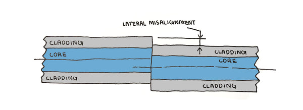
Lateral misalignment occurs when two optical fibers are offset. Lateral misalignment loss occurs when light from the core of the transmitting optical fiber enters the cladding of the receiving optical fiber, creating a loss. as the lateral misalignment increases, less light from the core of the transmitting optical fiber makes its way into the core of the receiving optical fiber, increasing the loss of the splice.
Even if the optical fibers are perfectly aligned, the splice may still experience loss from end separation. Separation is simply a gap between the transmitting and receiving optical fibers.
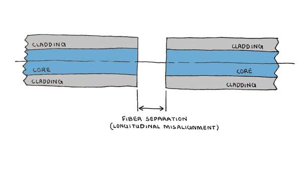
Separation can result in two different types of losses. The first is through Fresno reflection, which takes place when light passes from the higher refractive index of the core into the transmitting optical fiber into the lower refractive index of the air and then back into the core of the receiving optical fiber. Each change in the refractive index causes a certain amount of light to be reflected and therefore lost.
One way to overcome the effects of Fresno reflections in separated optical fibers is to use an index-matching gel, which is a transparent gel with a refractive index close to that of the core of the optical fibers being spliced. The gel fills the gap and reduces or eliminates the Fresno reflection. Matching gel is typically used for all mechanical splices.
Separation also causes loss because when light exists in the transmitting optical fiber, it spreads out like the light from a flashlight. Some of the light leaving the core of the transmitting optical fiber may enter the cladding of the receiving optical fiber, causing a loss. How much the light spreads out depends on several variables, including the distance between the optical fibers, the light source type, the launch type, the length and numerical aperture of the transmitting optical fiber, and the bends in the transmitting optical fiber.
If the optical fibers in a splice meet each other at an angle, a loss from angular misalignment may occur. The amount of loss depends on the severity of the angular misalignment and the acceptance cones of the transmitting and receiving optical fibers. Because the NA of a multimode optical fiber is greater than the NA of a singlemode optical fiber, multimode splices tolerate angular misalignment better than singlemode splices.

The loss from angular misalignment occurs when light from the core of the transmitting optical fiber enters the cladding of the receiving optical fiber or enters the core of the receiving optical fiber at an angle exceeding the acceptance angle. Light entering the core of the receiving optical fiber at an angle exceeding the acceptance angle may not propagate the length of the receiving optical fiber.
Angular misalignment also prevents the end faces from contacting each other, resulting in Fresnel reflections exactly like those described in the end separation that we talked about earlier. This is why index-matching gel is used with every mechanical splice.
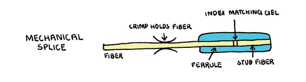
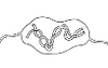
Many manufacturers offer mechanical splices. Mechanical spices like the ones shown in the image above are typically permanent; they align the two cleaved optical fibers and hold them in place. Index-matching gel inside the mechanical splice reduces or eliminates any fresnel reflections or losses at the splice connection.
Mechanical splices can be used for both singlemode and multimode fiber cables. Mechanical splices do not outperform fusion splices. However, they can outperform mated connector pairs. The key advantage of a mechanical splice over a fusion splice is the low cost of the equipment required to perform the mechanical splice.
The assembly tool that holds the optical fibers and the mechanical splice is relatively inexpensive when compared to the price of a fusion splicer. However, the actual mechanical splices cost considerably more than the protective sleeve required for a fusion splice.
Step 1: Fiber Preparation: Protective coatings, jackets, tubes, strength members, and other materials should all be removed, leaving only the naked fiber visible. The most important consideration is hygiene.
Step 2: Fiber Cleaning: It’s time to clean the raw fiber after it’s removed from its shell. The glass can be kept clean by wiping it with fiber optic cleaner and lint-free wipes.
Step 3: Cleaving the fiber: The process is comparable to fusion splicing cleaving; however, the accuracy of the cleave is less crucial.
Step 4: Joining fibers mechanically: This approach does not use heat. Simply place the fiber ends in the mechanical splice device and splice them together. Light coupling from one fiber end to the other will be aided by the index matching gel in the mechanical splice equipment.
Step 5: Fiber Protection: The final mechanical splice acts as its own splice protector.

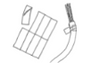
Fusion splicing uses a high-voltage electric arc between two electrodes to heat and melt the fiber ends together. This creates a permanent splice that is very fragile and must be protected from the outside environment and bending. This is typically accomplished using heat-shrink tubing and a small metal rod commonly referred to as a protective sleeve. Prior to performing the splice, the optical fiber is passed through the center of the protective sleeve, and the sleeve is positioned so it will not interfere with the fusion splicing process. After the fusion splices are successfully completed, the optical fiber is removed from the fusion splicer, and the protective sleeve is positioned directly over the splice area. The protective sleeve is then placed in an electric oven that is typically built into the fusion splicer. The oven heats the tubing, shrinking it around the fusion splice.
Fusion splicers are more expensive than the assembly tools required for mechanical splicing. However, they provide the lowest-loss fiber splice possible. In addition, fusion splices do not produce fresnal reflections. Fusion splicing is the most accurate and durable method for joining two optical fibers. After the optical fibers are stripped and cleaved, they are placed into the fusion splicer, where the two optical fibers are aligned between two electrodes. Depending on the fusion splicer used, several alignment techniques are used to align the fiber optic cable.
Fusion splicers on the market today typically feature a display that allows you to see the optical fibers on two different axes. The cameras in the fusion splicer magnify the optical fibers so that the end faces can be elevated. Most fusion splicers available today also have the ability to approximate the loss of the splice after it is completed.
Step 1: Fiber stripping: You must first remove or peel off the protective polymer coating around the fiber optic cable before you can begin fusing it. A mechanical stripping device, similar to stripping pliers, is usually used for this purpose. Remember to clean the stripping equipment before starting the fusing process.
Step 2: Fiber Cleaning: It’s time to clean the raw fiber after it’s removed from its shell. The glass can be kept clean by wiping it with fiber optic cleaner and lint-free wipes.
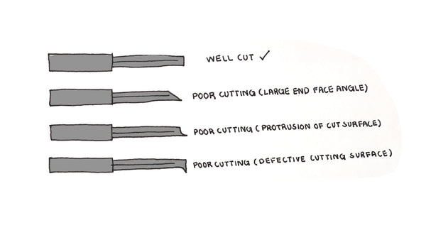
Step 3: Fiber Cleaving: To make an effective fusion splice, you need a decent cleaver. Instead of cutting the fiber, the chopper knife cuts, pulls, or bends it to cause a neat break, with the end face remaining flat and perpendicular to the fiber axis.
Step 4: Fiber Fusion: After the fibers have been stripped and cleaved, use a fusion splicer to join them together. The ends of the fiber must first be aligned within the splicer. Melt the fibers with an electric arc after they’re correctly aligned, permanently fusing the ends together.
Step 5: Fiber Protection: The splice will not break during typical handling if the fiber is protected from bending and tensile loads. The splice is protected from the weather and breakage by a protective sleeve placed in an electric oven that is typically built into the fusion splicer. The oven heats the tubing, shrinking it around the fusion splice.
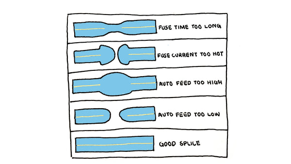
Now let's look at some variables of a fusion splice after it has been spliced, and let’s see what we can determine.
Here are some examples of what can happen when fusion splicing:
As you have now learned, how well a splice performs depends on many variables. As with mechanical splicing, these variables can be broken into two groups: intrinsic factors and extrinsic factors.
Intrinsic factors are the result of slight variations from one optical fiber to another. These variations can affect the performance of the splice even though the optical fibers are perfectly aligned when mated. Most optical fibers today have very little variation, which means there is a very small percentage of splice loss from intrinsic factors.
The most common factors in today's splice losses come from extrinsic factors related to the condition of the splice itself, external to the optical fiber. Oftentimes, they are caused by dirt and contamination. Microscopic particles of dirt can cause the misalignment of one or both optical fibers, creating a high-loss splice.
Let's consider five ways that can affect a fusion splice and why it is important to ensure these steps are followed in order to ensure a high-performance fusion splice.
We are going to look briefly at the following 5 ways:
The cleave angle is an important factor when it comes to fusion splicing. The endface of a properly cleaved optical fiber should be perpendicular to the optical fiber without any surface defects, and the cleave angle should not exceed 1.0 degrees. Here are some steps to consider in order to ensure a proper cleave angle.
Cleave length is just as important as cleave angle. Each fusion splice manufacturer defines how much bare optical fiber should be exposed after the cleaving process is completed. Exposing too much fiber or not enough fiber can create a high-loss fusion splice. In order to ensure a proper cleave length, it is important that the steps below are carefully followed.

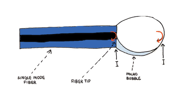
Dirt or entrapped air may cause a bubble or bubbles, resulting in a possible high-loss fusion splice. In order to prevent bubbles in your fusion splice, consider the following steps:
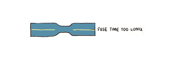
This is the term used to describe a fusion splice where the diameter of the fused optical fiber is smaller near the electrodes than it was prior to being fused. Necking is typically the result of to much heat during the prefuse, causing glass to be transported away from the splice area and thus producing a high-loss splice. In order to prevent necking, consider the following steps:
Contamination on the optical fiber or cleaver that is invisible to the human eye can still cause a fusion splice to exceed attenuation requirements, and this is especially true when it comes to singlemode fiber. Because you cannot see the contamination, make sure that you are using the types of cleaning products and the cleaning process required by the fusion splicer and cleaver manufacturer. It is also important to never let the cleaved fiber touch any surface after it has been cleaned; this will ensure the fiber does not attract dirt or dust on the surface.

Fusion and mechanical splicing are two very important aspects of fiber optic cabling. Both options have there use cases, and depending on the application, one may be better to use than the other. Fusion splicing does remain the better-performing option, and trueCABLE offers four different fusion splicing pigtail options when fusion splicing is needed in your fiber optic installation.
HAPPY NETWORKING!
trueCABLE presents the information on our website, including the “Cable Academy” blog and live chat support, as a service to our customers and other visitors to our website subject to our website terms and conditions. While the information on this website is about data networking and electrical issues, it is not professional advice and any reliance on such material is at your own risk.