No products in the cart.
Payment methods accepted
Unsure what Ethernet cable you need?
Look no further than our Ethernet Cable Finder. Answer a couple of questions and let trueBOT guide you to the perfect cable for any situation.
Still have questions? Check out our in-depth blogs, insightful white papers, and instructional videos on all things Ethernet cable and low voltage supplies.

Read: The Difference Between Cat6 vs Cat6A Ethernet Cable

Understand: Selecting the Correct Outdoor Ethernet Cable
Time to find coaxial cable and connectors for your install? Well, you are in the right spot!Check out our in-depth blogs, white papers, and instructional videos about everything going on in the low voltage industry and one of the best sources for coaxial information.
Have questions? Our networking experts have the answers!Check out our Cable Academy. for more information.

Read: The Difference Between Dual Shield vs Quad Shield Coaxial Cable
Understand: How To: Universal RG6 Compression F Connector on Quad Shield Coaxial Cable
Fiber Optic expertise at your fingertips.
Looking to deepen your understanding of fiber optic technology? Look no further than trueCABLE's Cable Academy. Our extensive collection of blogs, masterfully crafted by industry experts, offers a wealth of invaluable insights into the world of fiber optic cabling.
Have questions? Our networking experts have the answers.Check out our Cable Academy. for more information.
Read: Fiber Optic Splicing: Examining the Factors that Affect Splice Performance
Understand: Using Fiber Optics to Extend Your Ethernet Network Beyond Copper's Limits
Effortless cable management. Learn how we do it.
Low-voltage tools and accessories should keep your networking installations clean and organized. trueCABLE has a variety of high quality cable management tools, accessories and informative blogs for all your installation needs.
Check out our Cable Academy today and expand your knowledge.
Read: Copper Fabric Strips for Bonding Shielded Ethernet Cable
Understand: When Aliens Attack! Avoiding Ethernet Alien Crosstalk
Written by Dave Harris, trueCABLE Technical Specialist
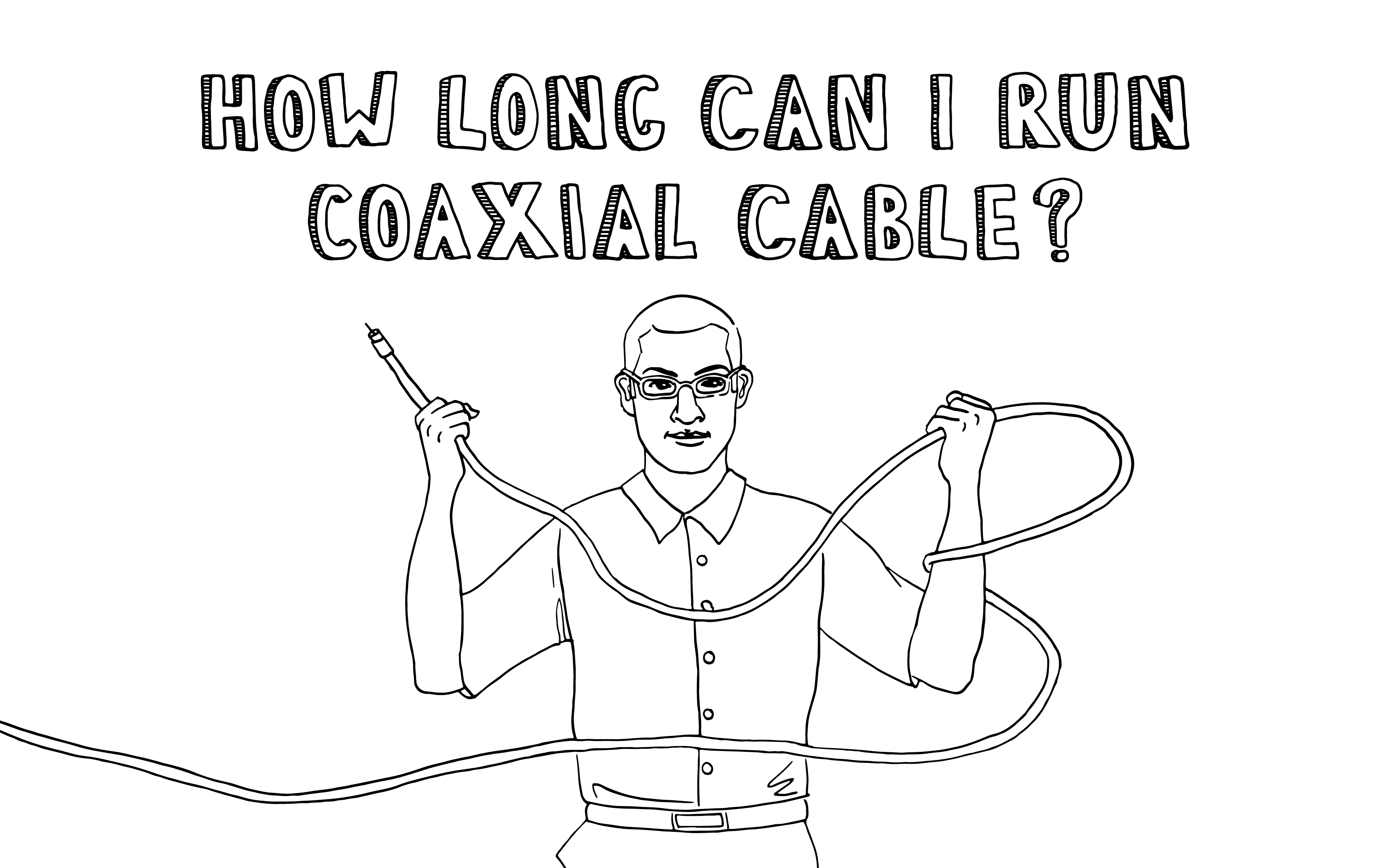
All day if you want to.
Back in the olden days, when there were three channels on TV (four if you count the educational channel), and closed-circuit transmissions consisted of low-resolution analog signals, it was possible to effectively run coaxial cable for hundreds and maybe even a thousand feet. I’m sorry to have to tell you this, but those days are pretty much over.

This bad news is due to the good things we have today that we didn’t have back then, such as broadband Internet and high definition digital television (HDTV). You see, the reason there are any limits at all to how far a cable can be effective is signal loss, also called attenuation. Attenuation in coaxial cable is mostly due to cable construction, distance of the circuit, and frequency of the signal. In short, for any given coaxial cable, the higher the frequency of the signal, the shorter the distance until the signal loss is too great to make use of what's left of the signal. Digital broadband and satellite systems operate at very high frequencies.
This is the part where most writers would whip out the really cool mathematical formula that lets you calculate attenuation based on frequency, distance, dielectric constant, conductor resistance, square roots, subscripts, greek letters, and neck pain. Because of severe mathematics-related childhood trauma, I’m not going to do that. I’m just going straight to the standards established by ANSI/TIA 568.4. The maximum supportable distances for broadband coaxial cabling applications are summarized in Table 1. “Series 6” refers to RG6 coaxial cable and “series 11” refers to RG11 coaxial cable.

**Take note these distances are inclusive of the patch cables too! The distances listed are the absolute maximum allowed from powered device to powered device. Known otherwise as the “channel”.
Remember that these are maximum values due to attenuation from the high frequencies of broadband signals and the design of the cables. Those are not the only factors that contribute to signal loss. In fact, just about everything you do to make coaxial cable useful adds even more to the total attenuation, further shortening the useful length of the cable. Every connector, splitter, and wall outlet adds to the total attenuation.
Insertion loss is really just what it sounds like. It’s the signal "loss” that happens as a result of “inserting” anything into the signal pathway. By “anything” I mean things like electronic devices, hardware, splices, ...anything.
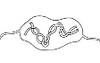
One of the biggest producers of insertion loss in a coax signal pathway is a splitter. A splitter is a device that splits the signal into two (or more) signals so that it can feed two devices, like when one antenna is shared between two TVs. This necessarily results in a large amount of signal loss, as each of those TVs are now only going to receive 50% of the signal it would have gotten if it had the antenna all to itself. Figure 1 shows how the splitter produces a signal loss of 50%. Signal strength (and signal loss) is expressed in units of decibels. Since we’re still avoiding PMSD (post mathematics stress disorder), Figure 1 also helps us to understand the decibel. After all the math is done, by somebody somewhere, it turns out that a 50% loss of signal strength is about equal to a loss of 3.5 dB.

That’s just for one splitter. Many homes have more than two TVs, some homes have quite a few TVs, and that means more splitters. As shown in Figure 2, addition of another splitter to the signal path doubles the attenuation to 7.0 dB, and cuts the signal strength in half again. So after the addition of the second splitter, we’re down to just 25% of the original signal strength.
All of those figures are for hypothetical splitters that operate at 100% efficiency which, of course, nothing really does. Also, each cable connection adds more attenuation due to signal leakage. These small signal losses are usually less than half a decibel, but they add up. Especially when you start including union fittings, wall outlets, a cable from the wall outlet to the set top box, the set top box itself, then a cable from the cable box to the TV. So as a rule of thumb, most installers expect each splitter to add between 3.6 dB and 4.0 dB to the total attenuation.

When coaxial cable is used to provide a home with both broadband internet and television service, the installer will usually route one of the outputs from the first splitter to the cable internet modem, and then use the other output to split further for multiple TVs. You can see why in Figure 2. This arrangement provides the strongest signal to the internet modem, which is where most users need the greatest bandwidth.
Now that we understand a little bit about decibels from looking at the effect of splitting the signal in half, we can talk a little bit more about attenuation of the cable. Remember that a signal loss of 50% is about equal to -3.5 dB and a loss of about -7.0 dB means that about 75% of the original signal is lost. Sticking with the same pattern, does a loss of -10.5 dB mean that almost 90% of the original signal is just gone? I’m afraid so.
So now let’s talk about some real-life frequencies and real-life distances. In the olden days of TV, the VHF channels 2-13 operated at frequencies of 54-216 MHz. Actually, they still do. When we look at that range of frequencies in Table 2, we can estimate that the signal loss for those channels is between about 1.5 dB and 3.1 dB, for a cable length of 100 feet. That’s well below the insertion loss from a single splitter, and one can imagine how longer cable distances are possible for VHF TV channels, especially for channels 2-5, which always seemed to come in best, right?

Compare that to the signal frequencies from satellite TV providers, which can be as high as 2150 MHz. At that frequency, attenuation of just the cable is almost 10 dB for that same 100 feet -- almost 85% of the original signal! And those are compressed signals. If we’re talking about real 1080p HDTV, the frequency is more like 3000 MHz, and over 100 feet of cable, it seems like there won’t be much signal left at all.
So if all you need are the soap operas from that old NBC affiliate on channel 4, then put your antenna out on the barn, down the road a piece, or even share it with your neighbors. But for today’s broadband cable Internet and television applications, keep your cable runs short, and the fewer splitters, the better.
trueCABLE presents the information on our website, including the “Cable Academy” blog and live chat support, as a service to our customers and other visitors to our website subject to our website terms and conditions. While the information on this website is about data networking and electrical issues, it is not professional advice and any reliance on such material is at your own risk.