No products in the cart.
Payment methods accepted
Unsure what Ethernet cable you need?
Look no further than our Ethernet Cable Finder. Answer a couple of questions and let trueBOT guide you to the perfect cable for any situation.
Still have questions? Check out our in-depth blogs, insightful white papers, and instructional videos on all things Ethernet cable and low voltage supplies.
Read: The Difference Between Cat6 vs Cat6A Ethernet Cable

Understand: Selecting the Correct Outdoor Ethernet Cable
Time to find coaxial cable and connectors for your install? Well, you are in the right spot!Check out our in-depth blogs, white papers, and instructional videos about everything going on in the low voltage industry and one of the best sources for coaxial information.
Have questions? Our networking experts have the answers!Check out our Cable Academy. for more information.
Read: The Difference Between Dual Shield vs Quad Shield Coaxial Cable
Understand: How To: Universal RG6 Compression F Connector on Quad Shield Coaxial Cable
Fiber Optic expertise at your fingertips.
Looking to deepen your understanding of fiber optic technology? Look no further than trueCABLE's Cable Academy. Our extensive collection of blogs, masterfully crafted by industry experts, offers a wealth of invaluable insights into the world of fiber optic cabling.
Have questions? Our networking experts have the answers.Check out our Cable Academy. for more information.
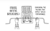
Read: Fiber Optic Splicing: Examining the Factors that Affect Splice Performance
Understand: Using Fiber Optics to Extend Your Ethernet Network Beyond Copper's Limits
Effortless cable management. Learn how we do it.
Low-voltage tools and accessories should keep your networking installations clean and organized. trueCABLE has a variety of high quality cable management tools, accessories and informative blogs for all your installation needs.
Check out our Cable Academy today and expand your knowledge.
Read: Copper Fabric Strips for Bonding Shielded Ethernet Cable
Understand: When Aliens Attack! Avoiding Ethernet Alien Crosstalk

Written by Don Schultz, trueCABLE Senior Technical Advisor, Fluke Networks Copper/Fiber CCTT, BICSI INST1, INSTC, INSTF Certified

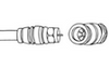
Bar none, one of the most challenging Ethernet cable terminations is the shielded Cat6 or Cat6A 8P8C (aka RJ45) connector. The challenges include getting a thick shielded cable to fit inside the connector and bonding the cable shield to the metal housing. Not a trivial task! Many different types of shielded 8P8C modular plugs exist, and they all fall short in one way or another. If you are like me, you want it all. So trueCABLE evaluated everything on the market, found the strengths and weaknesses, and then proceeded to design our own. You see, you can have your cake and eat it too.
Recommendation? I suggest you watch the video and read this blog as both bring their own level of detail to the table.
Design notes regarding the trueCABLE Cat6/6A Shielded Pass Through RJ45 Connector:

The “strict” fitment range of our shielded Cat6/6A passthrough 8P8C plug is 1.05 to 1.25mm (insulated conductor diameter). When matching up Ethernet cable it is important to land somewhere .03mm above minimum .03mm below maximum strict fitment range. Ideal fitment is with 1.08mm to 1.22mm insulated conductors to prevent fitment issues at the two extremes.
Can you use our Cat6/6A shielded external ground 8P8C plug on another manufacturer’s cable? Absolutely, but first, you should make certain that your cable will fit onto our modular plug. Check your cable’s specification sheet. You will want to look for insulated conductor diameters from 1.08 to 1.22mm and a cable jacket OD of 6.80 to 8.00mm. DO NOT rely on “Category” to determine 8P8C modular plug fitment. Category is technically irrelevant when it comes to modular plugs. For more information please see Selecting the Correct Connector.
trueCABLE puts a “Category” on our 8P8C modular plugs and associated documentation because we go the extra step of confirming fitment and performance with our cable. This makes “one-stop” shopping easy for our customers.
For those who would like to understand more about RJ45 plugs and why there can be such a great deal of confusion surrounding them, please read What is an RJ45 Connector?
Please note that attaching 8P8C (aka RJ45) plugs to solid copper Ethernet is the least stable way of terminating it for various reasons. Do not attempt to create patch cords (8P8C plugs at BOTH ends) with hand-terminated 8P8C plugs on solid copper Ethernet! One is OK, but the other end of the cable should be terminated to a patch panel and/or keystone jack.
Enough of that! Let’s jump right into terminating, shall we?
We will demonstrate this termination with trueCABLE Cat6A Shielded Plenum Ethernet cable. This cable has been fitment and performance tested as a system with our plug.

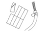
Tools of the trade
The glove and rod are to help with conductor straightening. The Copper Fabric Strips are to help ease cable shield bonding to your plug.
You might be wondering why trueCABLE places a strong recommendation on the dedicated trueGROUND tool for ground collar crimping as opposed to the built-in crimp cavities found on our All-In-One Crimp and Termination Tool. The reason can be found in Cat6/6A Shielded RJ45 External Ground Collar Crimping Done Right.
Pre-Step: Bend the external ground crimp/strain relief collar downward from the default position of 45 degrees to slightly past 90 degrees.

The idea is to get the collar out of your way
Next up:

Using our dedicated All-In-One Crimp & Termination Tool is one option for jacket stripping.. remove about 2.5” of jacket.
Since Ethernet cable jackets are not perfectly round, I learned a quick tip to make the end of the cable jacket (more) circular by rolling it between your thumb and index finger prior to stripping. It does help!
Now, pop the jacket open at the score and remove the jacket. Keep the jacket piece; it will be a free tool for at least five minutes. I promise.

Properly scored jacket being “popped”

Remove the cable jacket piece. Don’t toss the stripped off jacket piece just yet. Check for slices in the cable shield near the cable jacket edge. If you see any, you may have nicked a conductor. Keep your eyes open!

Make a small nip in the cable shield at the jacket.

Peel off and REMOVE the foil shield. You may discard the piece of foil.

Remove the rip cord.

Remove the PE wrap (polyester tape).

Check the conductors at the jacket edge for nicks. Nicks show up as slices in the conductor insulation or even bright copper. If you see nicks, start over. Note: Copper Fabric Strip shown already applied in this photo.

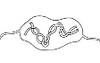
Wrap the ESD drain wire backwards and around the cable jacket in a spiral fashion. Apply a Copper Fabric Strip to tack down the ESD drain wire. Skip about 3/16” from the jacket edge so that some cable jacket color still remains. This will help with seating depth in the plug housing.

Remove the spline by making four snips. Rest the clippers on the cable jacket edge and snip each “wing” downwards. Be careful not to nick a conductor. DO NOT remove the spline by cutting straight across--it will make termination more difficult.
The internal spline is found on all trueCABLE Cat6 and Cat6A cables. The purpose is to improve performance by reducing pair to pair crosstalk. We did not add it to make your life difficult!

Twist spline to remove.
Copper Fabric Strip applied and the spline removed. Now you are ready to untwist the conductor pairs.

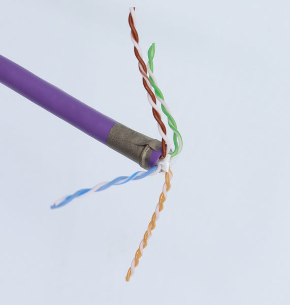
Use the piece of cable jacket you stripped off to untwist the conductor pairs.

Straighten the conductors out by removing the kinks. You may use a smooth metal shaft or the back hard plastic of your clippers. A glove is helpful here to protect your thumb!
DO NOT overwork the conductors. Use one or two passes at most. If you overwork the conductors you may thin-out the copper conductors or remove the conductor insulation.

Conductors smoothed out. This is the time to put them into either the T568A or T568B sequence. We will use the T568B sequence for this blog, which is most commonly used by installers today.
Here is a handy reference for you. When looking at the conductor color sequence, be sure you understand the orientation of the plug itself! Yes, it is quite possible to get the sequence correct and put the plug upside down. I have done it, so don’t be a Don.

T568A and T568B color code chart for your reference!

Line up the conductors and then flush cut about ½” off. Leave about 1.5” of conductor excess. You may cut straight across or on an angle as you prefer. Once the conductors are in sequence and flush cut, maintain control of the conductors or they will get out of sequence!

Begin inserting the conductors into the plug housing.
There is a plastic “stop ledge” inside the plug housing. Be careful to not ram the conductors into that ledge or you will need to pull the conductors out and straighten them again. The conductors will start to “stagger” for you once you reach the end of the plug near the golden contact pins.

Continue pushing the conductors until they protrude from the nose, but don’t fully seat the cable jacket into the housing yet. Check the color sequence again to be sure none of the conductors got out of order.

Insert the cable jacket into the plug housing to the depth indicated. You will feel a hard stop point. You want to see a small amount of cable jacket color just after the metal. Stop there.
DO NOT attempt to seat the cable jacket any deeper or you risk distorting the plug housing. This pass-through plug is designed to set the ½” ANSI/TIA untwist limit but not tighter. Extensive testing by trueCABLE has shown no significant benefit to deeper seating on RJ45 terminations.

Cable jacket is seated to the correct depth and conductors are in the correct sequence. DO NOT terminate the plug yet.

Hinge the ground collar back upward and inline with the cable jacket and plug housing.

How the ground collar should look prior to folding down the wings.

Using a flat blade screwdriver, bend the ground collar “wings” downward as shown to pre-start the crimp.
Important: First crimp the ground collar and then terminate the golden contacts in the termination tool.

Place the assembly into the trueGROUND tool and use the large crimp cavity to fully compress the ground tab.

Fully compressed and crimped ground collar. If it does not look like this, then it is not done correctly!
Why do we recommend crimping the ground collar down FIRST before terminating the golden contacts? Extensive experience with this style of RJ45 plug has demonstrated that crimping the ground collar before terminating the contacts places much less stress on the golden contacts and helps to preserve performance.

Now you can terminate the plug.
It is very helpful to push the plug into the crimp cavity with moderate force, being certain it is fully seated. DO NOT use excessive force. Hold the cable and plug assembly while starting to collapse the tool handle. Once the process has started you should remove your hand and then fully compress the handle. The reason you want to remove your hand at the last moment is to permit the strain latch presser bar to adjust the plug into the tool for proper termination and flush cutting.
No matter what you do, do not use a high degree of force on the cable and plug assembly while closing the tool handle. This will result in a damaged plug!

Completed termination. See table below for areas to check and why.
A - Ground collar. The ground collar should be perfectly compressed as shown. It should slightly indent the cable jacket. It must be perfect as it is the only strain relief mechanism!
B - Seating depth. The cable jacket color should show about 1/16” after the metal. It should not be seated any closer to the golden contacts or you risk damaging the plug.
C - Golden contacts. The golden contacts should be fully seated. Check for popped up pins.
D - Flush cut. The conductors should be fully flush cut off. You can run your finger across the front of the plug to be sure. A slight under-cut to the nose “tab” of about 1 mm is normal. The tool is designed to under-cut and bite into the nose slightly to ensure full flush cuts.
All done! So, there you have a Cat6/6A shielded external ground RJ45 connector on your cable now. Go plug it in and HAPPY NETWORKING!
Wait!
Something not right? Is your cable not performing to your expectations? You could have a bad or poorly terminated RJ45 plug. Better check out What Does a Bad Termination Look Like?
trueCABLE presents the information on our website, including the “Cable Academy” blog and live chat support, as a service to our customers and other visitors to our website subject to our website terms and conditions. While the information on this website is about data networking and electrical issues, it is not professional advice and any reliance on such material is at your own risk.