No products in the cart.
Payment methods accepted
Unsure what Ethernet cable you need?
Look no further than our Ethernet Cable Finder. Answer a couple of questions and let trueBOT guide you to the perfect cable for any situation.
Still have questions? Check out our in-depth blogs, insightful white papers, and instructional videos on all things Ethernet cable and low voltage supplies.
Read: The Difference Between Cat6 vs Cat6A Ethernet Cable

Understand: Selecting the Correct Outdoor Ethernet Cable
Time to find coaxial cable and connectors for your install? Well, you are in the right spot!Check out our in-depth blogs, white papers, and instructional videos about everything going on in the low voltage industry and one of the best sources for coaxial information.
Have questions? Our networking experts have the answers!Check out our Cable Academy. for more information.
Read: The Difference Between Dual Shield vs Quad Shield Coaxial Cable
Understand: How To: Universal RG6 Compression F Connector on Quad Shield Coaxial Cable
Fiber Optic expertise at your fingertips.
Looking to deepen your understanding of fiber optic technology? Look no further than trueCABLE's Cable Academy. Our extensive collection of blogs, masterfully crafted by industry experts, offers a wealth of invaluable insights into the world of fiber optic cabling.
Have questions? Our networking experts have the answers.Check out our Cable Academy. for more information.
Read: Fiber Optic Splicing: Examining the Factors that Affect Splice Performance
Understand: Using Fiber Optics to Extend Your Ethernet Network Beyond Copper's Limits
Effortless cable management. Learn how we do it.
Low-voltage tools and accessories should keep your networking installations clean and organized. trueCABLE has a variety of high quality cable management tools, accessories and informative blogs for all your installation needs.
Check out our Cable Academy today and expand your knowledge.
Read: Copper Fabric Strips for Bonding Shielded Ethernet Cable
Understand: When Aliens Attack! Avoiding Ethernet Alien Crosstalk

Written by Ben Hamlitsch, trueCABLE Technical and Product Innovation Manager RCDD, FOI
When talking about fiber, optical return loss (ORL) is one of the key measurements tested in a fiber link. Optical return loss is the amount of light that is reflected back to the source, this reflected light is measured at each connector and splice at each point over the entire fiber link. This is always measured in dB (decibels) and will be displayed as a negative number. The closer the number is to zero, the higher the reflectance (meaning a poor connection). There are many different reasons that can cause poor reflection in a fiber optic system. We will look at some of these to give you a better idea of what to do to ensure you have the least amount of return loss in your network. We will touch on what tool is used to measure this, as well as some different types of loss (such as return loss) and what reflectance is in a link.
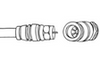
Here is where we discuss several of the factors that contribute to high return losses. In fiber optics, it is imperative that you make sure you are always inspecting and cleaning the fiber optic connectors before you mate them together. Dirt, dust, grease, and smudges on the connector face is the number one cause of high return loss, but can be the easiest to prevent if done properly. We all know that wiping a fiber connector on a shirt may seem like a viable and quick option; however, it is not the proper or correct way to clean your connector. With how small the core of single mode fiber is (9um), even the tiniest dust particle can wreak havoc on your optical signal. Using 99% reagent grade isopropyl alcohol and lint free tissues is one way to clean properly. There are also fiber click cleaners that assist the mating sleeve in cleaning the face of a connector.
Another thing that will cause a high return loss is a broken or cracked piece of fiber. Some pieces of fiber can have a small crack that will go somewhat undetected when preforming a insertion loss test. This is because insertion loss tests give you a loss value of the overall cable link and not at each individual component. The advantage of testing that implements return loss and reflection can really help to avoid a bigger headache down the line.
Poorly mated connectors are another cause of high return loss that can lead to other problems if not corrected. If the connectors are not fully inserted, this can lead to air gaps between the two mated connectors, which in turn will lead to high loss. This type of problem can have low insertion loss but will be a problem if the loose connectors become misaligned or even disconnected. If the mated connectors become disconnected, it can cause a complete loss of signal that will take your network down. So when you see a high return loss at a pair of mated connectors, this should be a red flag and some troubleshooting should be in order.

When looking at your overall Optical Return Loss, you have several events that happen in a link. These events as individual occurrences are known as reflectance events. A mated pair of connectors is a reflectance event that happens in a fiber link. The type of polish that a connector end face has will affect the amount of return loss and insertion loss for that particular event. When you are looking at these reflectance events, the closer to zero your measured event result is, the poorer the connection will be, which results in more insertion loss and higher return loss. Below are some different types of reflectance figures and the average amount of reflection you should see when tested at these different polish types. The reflectance value is always displayed as a negative dB figure.
We know that the closer to zero a reflectance event is, the worse it is for return loss. Let's look at angle polish connectors (APC) as compared to a fusion splice. When doing single mode long haul applications, having low return loss is very important so the fiber link will be able to cover the distance that is needed with the minimal amount of light loss. Looking at the APC connector, we see that the typical reflection is -60dB (the furthest away from zero), meaning it has very little reflection, causing the amount of loss to be less or better. We can compare this to the fusion splice, which has the same value as the angled polish connector, this is the reason why, in a long-distance application, splicing is used and APC connectors are the preferred choice in these fiber applications.
Why is all the information above important and relevant to your network and fiber optic links? In all networks, the end goal is to be able to carry your signal from point A to B with minimal loss over fiber link. If you have high return loss, this may cause distortion of your signal, interruption of transmission or even worse - shut down your network completely. The tool that everyone should have to take optical return loss measurements is an Optical Time Domain Reflectometer (OTDR). An OTDR allows you to measure your entire link, and will even give you a map that will tell you at what distance the pair of connectors are that need to be cleaned or just checked to make sure they are not loosely mated together. It is a key piece of equipment and will be discussed in more detail in this article.
As we mentioned earlier reflection refers to the phenomenon where a portion of the light that is transmitted through the fiber is reflected back into the fiber. This can occur at the interfaces between different materials with different refractive indices, such as at the interface between the core and cladding of an optical fiber, or where two connectors are mated together.
Reflection is an important consideration in fiber optics because it can cause signal loss and degradation of the fiber link. When light is reflected back into the fiber, it travels in the opposite direction and can interfere with the forward-traveling signal, causing attenuation. In addition, reflections can cause standing waves, which can lead to signal distortions.
To minimize reflection in fiber optics systems, it is important to use fiber optic cables with low reflection loss and to properly terminate the fibers to reduce reflection at the connectors. This can be done using techniques such as angle polishing and anti-reflection coatings.
The OTDR gives reflectance measurements at any event location along the fiber link. This could be a splice event or a connection between two mated connectors.
It is important to note that when ORL/Reflection is tested, the test will show a negative value. In the chart below, you can see reflection values. The higher the negative number, the better the reflectance. So when it comes to low reflectance, the APC connector has the best performance of all connector types.

The amount of light reflected at a connection between two fibers is determined by the differences in the index of refraction of the two fibers connected, a function of the composition of the glass in the fiber or air in the gap between the fiber connectors, as is common with connector terminations and mechanical splices. Connectors will show reflectance peaks on OTDR traces; mechanical splices typically will also show reflectance peaks; and fusion splices will most often show no reflectance or sometimes with just a small dip in the location of the fusion splice.

In an OTDR, the peak that identifies a reflective event is measured and reflectance calculated. Higher peaks indicate higher reflectance. In order to measure reflectance, the peak must not saturate the OTDR receiver, as indicated by a flat-topped reflectance peak (below). For instance, this is an OTDR trace where reflectance cannot be accurately measured. It will only indicate a value less than the actual. However if this is the case you can always guarantee that the reflection at this event needs to be looked and there will need to be some investigation into what is causing this high reflectance.

Calculating reflectance in an OTDR is a complicated process involving the baseline of the OTDR, the backscatter level, and the power in the reflected peak, as shown in the diagram below. Since reflectance is defined as a fraction of the power in the test signal, the OTDR must calculate the test power from the backscatter level of the fiber, based on the typical backscatter coefficient of the fiber being tested. In other words it uses lots of fancy calculations to make these detailed and precise measurements.

Which method to use will depend on the specific needs of the application and the type of information that is desired.
Optical Return Loss and reflective events, are a very important measurement in fiber optic cabling systems. This measurement parameter can tell the technician a lot about what is wrong with a fiber optic network, because it breaks it down to the individual connector and splice giving the technician much more detail to troubleshoot an issue. Modern day OTDR’s are designed to test for reflection loss and give a user-friendly graphical interface where the technician can easily and quickly troubleshoot the fiber link. Good installation practices can ensure that the Optical Return Loss/Reflectance is as low as possible for any given fiber cable link.
STAY CONNECTED!
trueCABLE presents the information on our website, including the “Cable Academy” blog and live chat support, as a service to our customers and other visitors to our website subject to our website terms and conditions. While the information on this website is about data networking and electrical issues, it is not professional advice and any reliance on such material is at your own risk.